EN
EN Español
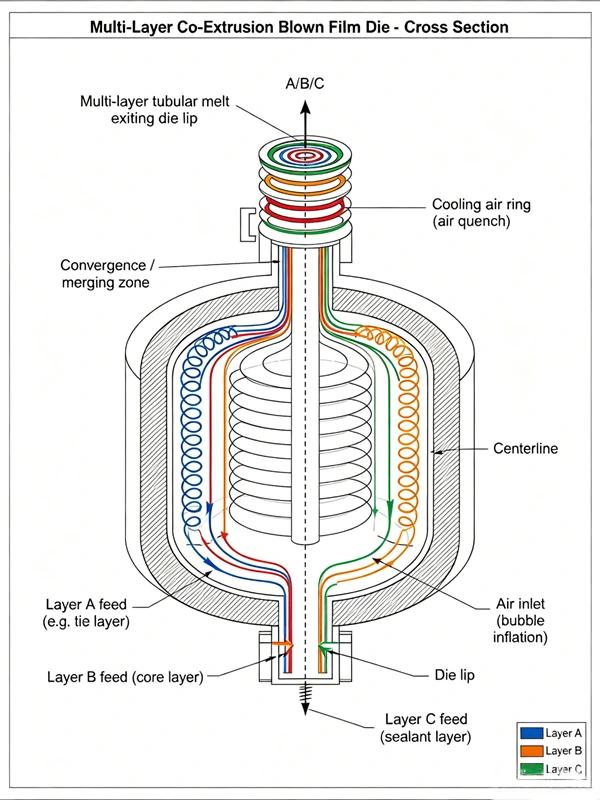
A co-extrusion blown film die is an annular precision component that receives two or more separate polymer melt streams from individual extruders, distributes each melt uniformly around a circular circumference, and combines them into concentric layers just before the die exit. The quality of the final multilayer film depends primarily on three factors: how evenly each melt is distributed around the die circumference, how stable the interfaces between adjacent layers remain during flow, and how precisely the temperature of each melt stream is controlled throughout the die body. This article explains the internal working principles of co-extrusion dies — from spiral mandrel flow channels to layer merging zones — and outlines the key design parameters that determine layer uniformity in blown film production.
Why Multilayer Film Requires a Specialized Die
A single-layer blown film die receives one melt stream and shapes it into a uniform annular tube. A co-extrusion die must accomplish a fundamentally more complex task: managing multiple melt streams that may have different viscosities, different optimal processing temperatures, and different flow behaviors, and bringing them together without disturbing the uniformity of any individual layer.
The core engineering challenge is that each polymer has its own rheological profile. When two polymer melts with different viscosities flow side by side through a channel, the lower-viscosity melt tends to migrate toward the region of highest shear rate — typically the channel wall — while the higher-viscosity melt concentrates in the center. This phenomenon, known as viscous encapsulation, can distort layer boundaries and create thickness variations that affect film performance.
A co-extrusion die is designed specifically to manage this challenge: to distribute each melt into a uniform annular form before the layers converge, so that interface distortion is minimized at the point of combination.
Inside the Die: From Melt Entry to Layer Formation
A co-extrusion blown film die performs four sequential functions: melt reception, circumferential distribution, layer convergence, and final shaping. Understanding these stages helps explain why die design decisions have such a direct impact on film quality.
Stage 1: Melt Reception
Each extruder feeds its melt into the die through a separate entry port. In a side-fed die, extruders approach from the side, perpendicular to the die axis. In a stack die (also called an inline die), extruders feed along the die axis. Stack dies are mechanically more complex but tend to achieve more symmetric melt distribution because the feed geometry is inherently balanced.
Stage 2: Circumferential Distribution
Once inside the die, each melt must be spread from a single entry point into a uniform ring around the full circumference. The most widely used mechanism for this is the spiral mandrel — a cylindrical or conical component with helical grooves machined into its surface. Each melt stream enters the spiral groove, and as it travels along the helix, the groove depth gradually decreases. Melt progressively leaks out of the groove into the clearance between the mandrel and the die body, forming a uniform annular flow layer.
The spiral mandrel design is governed by several geometric parameters: the number of helical grooves, the initial groove depth and width, the helix angle, and the clearance gap. Each of these parameters affects the pressure distribution and flow uniformity within that specific layer. Computational fluid dynamics (CFD) simulation is commonly used during die design to optimize these parameters before manufacturing.
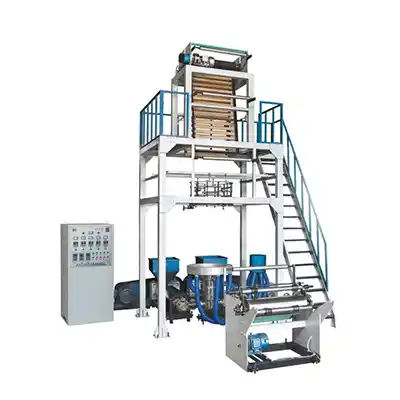
For a deeper look at the equipment configurations that incorporate these die designs, the film blowing machine overview provides the full product range context.
Stage 3: Layer Convergence
After each melt has been distributed into a uniform annular flow, the individual layer streams converge in a common flow channel near the die exit. This convergence zone is the most critical region of the die for interface quality. If the melts merge under mismatched flow conditions — different linear velocities, different pressures, or significantly different viscosities — the resulting interfaces may be wavy, uneven, or unstable.
Well-designed convergence zones use gradual channel geometry transitions to minimize sudden changes in shear rate. The goal is to bring the layers together under similar shear stress conditions so that each layer maintains its intended thickness around the full circumference.
Stage 4: Final Shaping at the Die Lip
The converged multilayer structure then passes through the final die lip gap, which sets the total extrudate thickness. The lip gap also influences the shear rate experienced by the outermost layers and therefore affects surface quality and optical properties.
Spiral Mandrel vs. Stacked Die: A Comparison
| Feature | Spiral Mandrel Die | Stacked (Inline) Die |
|---|---|---|
| Melt feed orientation | Side-fed (perpendicular to die axis) | Inline (along die axis) |
| Layer flexibility | Each layer needs its own mandrel | Layers added by stacking modules |
| Flow uniformity | Generally more uniform circumferential distribution; higher pressure loss | Lower pressure loss but can be less uniform at large diameters |
| Mechanical limitation | Larger outlet diameters achievable | Stackable structure limits outlet diameter |
| Purge and cleaning | More complex internal channels | Conical stackable mandrels improve purgeability |
| Common application | Standard ABA/ABC blown film dies | High-layer-count and specialty film dies |
Spiral mandrel dies achieve more uniform melt distribution at the outlet compared to flat spiral dies, though flat spiral dies typically exhibit lower pressure loss.
Layer Thickness Control: What Determines the Ratio
Achieving a target layer thickness ratio — for example, a 20% sealing layer, 60% core layer, and 20% outer layer — depends on several interacting factors:
Melt pump rate per extruder. The output rate of each extruder determines how much material is available for each layer. Precise screw speed control is essential.
Flow channel resistance. The geometry of each layer's flow path — channel cross-section, length, and clearance — determines the pressure drop and therefore the flow rate for that layer at a given melt pressure.
Melt viscosity at die temperature. Because viscosity varies with temperature and shear rate, the actual flow resistance of each layer changes with operating conditions. A layer running at a higher temperature may flow more easily, increasing its share of total output.
Die temperature uniformity. Non-uniform die temperature around the circumference creates local viscosity variations that produce circumferential layer thickness deviations.
The relationship between extruder output and layer thickness is not linear across all operating conditions. Buyers should verify layer ratio control capability with the equipment supplier under their specific material and output requirements.
Temperature Profile: The Often-Overlooked Variable
Each polymer requires a specific melt temperature range for optimal flow. When co-extruding materials with different processing windows — such as a low-melting-point sealing resin and a higher-melting-point barrier resin — the die must maintain separate temperature zones for different melt channels.
Typical die temperature ranges vary by material. For LLDPE, the processing temperature range is commonly cited as 160°C to 220°C, while HDPE may require 180°C to 240°C depending on the grade and die configuration. These values depend on the specific resin grade, melt index, and die design, and should be confirmed with both the resin supplier and the equipment manufacturer.
In multi-channel dies, poor thermal isolation between zones can cause heat transfer between adjacent melt streams, shifting viscosities and altering layer thickness ratios. This is one reason why die heating systems use independently controlled zones with thermocouples positioned at multiple points along each melt channel.
Common Die-Related Defects and Their Root Causes
| Defect | Typical Root Cause |
|---|---|
| Uneven layer thickness around circumference | Non-uniform spiral mandrel distribution; die temperature variation; partial groove blockage |
| Interfacial waviness or "dancing" bubble | Mismatched viscosities at convergence point; insufficient shear stress at interface |
| Gels or fisheyes | Overheated/degraded polymer residue in die channels; contamination |
| Die lines (longitudinal streaks) | Die lip damage; melt buildup at die exit |
| Poor optical clarity | Inadequate quenching after die exit; die lip surface condition |
| Layer encapsulation (one layer wrapping another) | Viscosity ratio too extreme between adjacent layers; incorrect layer ordering |
The most common issues trace back to three sources: melt temperature control, channel cleanliness, and viscosity matching between adjacent layers.
A Practical Die Inspection Checklist
- Verify die temperature setpoints match the resin supplier's recommended processing window for each layer
- Check for circumferential temperature variation using a surface pyrometer at multiple points around the die body
- Inspect die lip for scratches, buildup, or polymer degradation deposits
- Confirm that spiral mandrel grooves are clear of degraded material (requires die disassembly during scheduled maintenance)
- Review layer thickness measurements from at least four circumferential positions, not just one
- Confirm that extruder output rates are stable before adjusting die parameters
- When changing material grades, purge the die thoroughly before evaluating layer quality
FAQ
Q: How many layers can a single co-extrusion blown film die produce?
A: Standard production dies typically handle two to three layers (AB, ABA, ABC configurations). Higher layer counts — five, seven, or more — are possible with specialized die designs, but each additional layer increases die complexity and requires additional extruders and melt channels. For most flexible packaging applications, three layers provide sufficient functionality for sealing, strength, and barrier requirements.
Q: Why does layer thickness vary around the circumference even when the die is new?
A: Even well-manufactured dies can exhibit circumferential thickness variation if die temperature is not uniform. A difference of a few degrees between one side of the die and another changes melt viscosity locally, which alters flow distribution. Always verify temperature uniformity before assuming a mechanical die issue. The extrusion monitoring systems available on modern blown film lines can help track this.
Q: Can a co-extrusion die run the same material in all layers?
A: Yes. Running identical material in all layers is sometimes done during startup, purging, or when producing thick films where the multilayer structure provides mechanical benefits without requiring different materials. However, this approach does not leverage the primary advantage of co-extrusion, which is combining different material properties in a single film.
Q: What is the difference between a feedblock and a multi-manifold die?
A: A feedblock combines separate melt streams into a layered structure before they enter the die. A multi-manifold die keeps each melt stream separate until just before the die exit, distributing each melt independently around the circumference. Multi-manifold dies provide better layer thickness control for materials with very different viscosities. Feedblock systems are simpler but are more sensitive to viscosity mismatches. The review of available configurations can help clarify which approach suits specific production requirements.
Q: How does die design affect bubble stability?
A: Die design influences bubble stability primarily through two mechanisms: the uniformity of melt distribution around the circumference, and the thickness consistency of the outermost layer. An uneven melt distribution creates local thickness variations that cause differential cooling and lead to bubble movement. Well-distributed melt and consistent die lip temperature are prerequisites for stable bubble operation. For producers running ABA structures, the layered symmetry inherent in A/B/A designs can assist with balanced cooling and consistent film flatness; the ABA machine specifications provide relevant technical parameters.
Q: When should a die be disassembled for cleaning?
A: Die disassembly frequency depends on the materials processed, production hours, and contamination levels. As a general guideline, dies should be inspected during scheduled maintenance intervals — commonly after several hundred production hours — or whenever film quality indicators such as gels, die lines, or unexplained thickness variation appear. Following material changeovers, especially when switching between incompatible polymers, a full die purge and inspection is advisable.
Conclusion
The performance of a co-extrusion blown film die is determined by how well it distributes each melt around the circumference, how stably it brings layers together, and how precisely it maintains temperature across multiple flow channels. Buyers evaluating multilayer film production capabilities should prioritize understanding the die's internal flow design — spiral mandrel configuration, convergence zone geometry, and thermal zoning — rather than focusing solely on the number of extruders or total output capacity.
When die-related quality issues arise, the most productive starting point is verifying temperature uniformity and melt pressure stability before assuming a mechanical defect. Many layer thickness and bubble stability problems trace back to thermal or flow-rate variables that can be corrected without die modification.
For production requirements that involve specific material combinations or layer structures, discussing the melt flow characteristics and processing window with the equipment supplier before finalizing die specifications is the most reliable path to consistent film quality.
 Brochure Download
 FAQ
FAQ