EN
EN Español
An IBC (Internal Bubble Cooling) system circulates cooling air inside the film bubble, working alongside the external air ring to remove heat from both sides of the film simultaneously. In a three layer configuration, this dual-side cooling accelerates frost line formation, improves thickness uniformity, and supports higher extrusion output. Setup requires coordinated attention to air volume, bubble diameter sensors, frost line height, and layer ratio confirmation—each of which directly affects film quality and production stability.
Why Three Layer Film Needs Better Cooling
Three layer co-extrusion produces a tubular film with distinct functional layers: an outer layer for printability or stiffness, a core layer for strength or barrier, and an inner layer for sealing. Each polymer layer has different thermal properties, melt temperatures, and crystallization behavior. When these layers exit the die as a single composite tube, the cooling process determines whether the layers bond properly, whether the film maintains consistent gauge, and whether the final roll meets downstream converting requirements.
External air ring cooling alone can handle standard mono-layer output rates. At the higher throughput and tighter gauge tolerances expected from three layer lines, the film's internal surface retains heat longer, delaying frost line formation and limiting production speed. IBC addresses this bottleneck by actively managing the air inside the bubble rather than allowing it to remain stagnant.
How IBC Works in a Three Layer Blower
IBC systems use an air inlet and exhaust mechanism mounted through the die head. Cooled air is introduced into the bubble interior, travels upward along the inside film surface, and exits through an exhaust port, carrying absorbed heat away from the film. An ultrasonic sensor tracks bubble diameter and adjusts air volume to maintain a stable circumference.
In a three layer setup, the IBC system works in coordination with the die head's internal passages and the external dual-vent air ring. The external air ring cools the outer surface, while IBC cools the inner surface. This combined approach produces faster, more uniform cooling across the full film thickness.
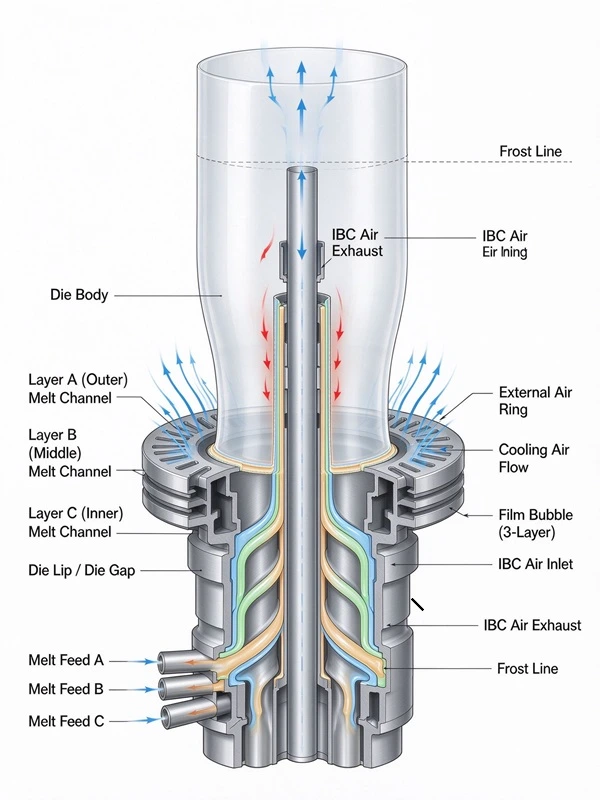
The key difference between IBC and non-IBC operation is active versus passive interior air management. Without IBC, the air trapped inside the bubble heats up and stays largely stagnant, limiting heat transfer. With IBC, a controlled exchange of cool inlet air and heated exhaust air maintains a consistent cooling gradient along the bubble.
Benefits of IBC on Three Layer Lines
Improved thickness uniformity. By cooling both film surfaces at a controlled rate, IBC reduces the temperature differential across the composite structure. This helps minimize gauge variation and supports more consistent layer distribution.
Faster frost line formation. The point at which the molten film solidifies (the frost line) occurs closer to the die when IBC is active. A shorter and more stable frost line contributes to better bubble stability and allows higher extrusion rates without sacrificing film quality.
Higher output within existing floor space. Production data from equipment manufacturers indicate that adding IBC to an existing blown film line can increase output by a meaningful margin compared to external-air-ring-only cooling. The exact gain varies by material, die design, and line configuration, and should be verified through on-site testing.
Better bubble diameter control. Ultrasonic sensor feedback combined with IBC air volume adjustment provides tighter control over bubble circumference, which directly affects layflat width consistency and edge trim waste.
Film clarity and optical properties. Faster cooling can reduce surface irregularities that form when the film remains molten longer. The trade-off is that faster cooling may increase the risk of freezing in minor surface defects, so air volume and temperature must be balanced against the target film specification.
IBC vs External Air Ring Only: A Practical Comparison
| Factor | External Air Ring Only | With IBC System |
| Cooling surfaces | Outer surface only | Both outer and inner surfaces |
| Frost line height | Higher (further from die) | Lower and more stable |
| Thickness uniformity | Depends on air ring uniformity | Improved via dual-side cooling |
| Maximum practical output | Limited by heat removal capacity | Supports higher extrusion rates |
| Bubble diameter control | Manual or basic sensor feedback | Ultrasonic sensor with active air volume adjustment |
| Startup complexity | Simpler | Requires coordinated air volume and sensor calibration |
| Film optical quality | Standard | May improve clarity; requires parameter tuning |
| Best suited for | Mono-layer, low-to-medium output | Multi-layer, higher output, tighter gauge requirements |
The table above summarizes general process relationships. Actual results depend on die design, material formulation, air ring configuration, and operating conditions. Buyers should request performance verification for their specific material and target specifications.
Three Layer IBC Setup: Step-by-Step
Setting up a three layer IBC line requires coordination between extrusion parameters, cooling air management, and bubble geometry. The following sequence reflects standard industry startup practice:
Step 1: Confirm layer ratio and material distribution. Before startup, verify that each extruder is assigned the correct material and that the target layer ratio (e.g., 20% outer / 60% core / 20% inner) has been entered into the control system. Layer ratio directly affects cooling behavior because different polymers have different heat capacities.
Step 2: Establish base extrusion parameters. Set screw speeds and barrel temperatures according to the material supplier's recommendations. For HDPE, typical barrel temperatures range from 180–220°C; for LDPE, 160–200°C. Three layer lines often run different temperature profiles for each extruder.
Step 3: Start the bubble at low speed. Begin extrusion at reduced screw speed. Once the molten tube emerges from the die, introduce air through the IBC inlet to inflate the bubble. Adjust air volume gradually until the bubble reaches the target diameter.
Step 4: Activate external air ring. Turn on the external air ring and adjust airflow to match the bubble size. The external air ring and IBC should work together—not against each other—to maintain a stable bubble.
Step 5: Set frost line height. Monitor the frost line visually and through the line's control interface. Adjust IBC exhaust rate and external air ring volume to bring the frost line to the target height. Small adjustments are preferred; large swings in air volume can cause bubble instability.
Step 6: Calibrate IBC sensor and diameter control. Once the bubble is stable, engage the ultrasonic diameter sensor and let the automatic control loop manage air volume. Verify that the sensor reads the correct diameter and that the control response is neither too aggressive nor too slow.
Step 7: Run thickness and width checks. After the line reaches stable operation, measure film thickness across the web and verify layflat width. Adjust die bolts or layer ratios as needed. Confirm that edge trim is within acceptable limits.
Step 8: Document the recipe. Record all parameters—extruder speeds, temperatures, IBC air volume, external air ring settings, frost line height, and diameter setpoint—as the baseline recipe for this material and product specification.
Common Setup Issues and What They Indicate
| Symptom | Likely Cause | Check |
| Bubble fluctuates in diameter | IBC air volume too high or sensor response too fast | Reduce IBC supply rate; recalibrate sensor |
| Frost line too high | Insufficient total cooling | Increase IBC exhaust or external air ring volume |
| Frost line oscillates up and down | IBC sensor issue or ambient temperature changes | Check IBC sensor height; stabilize workshop airflow |
| Film thickness varies across web | Uneven cooling or die gap issue | Check IBC air distribution; verify die bolt settings |
| Bubble breaks during startup | IBC air volume too high for material melt strength | Start with lower air volume; increase gradually |
| Film blocking on winder | Residual heat in inner layer | Increase IBC cooling; reduce line speed briefly |
These relationships represent general troubleshooting logic. Specific root causes should be confirmed through systematic parameter adjustment and, where necessary, consultation with the equipment supplier.
IBC Setup Checklist
- Layer ratios and material assignments confirmed for all three extruders
- Barrel temperatures set per material supplier recommendations
- IBC inlet and exhaust tubes properly seated and leak-free
- External air ring airflow verified as uniform around the bubble
- Frost line target height determined for the material and thickness
- Ultrasonic diameter sensor calibrated and reading correctly
- Bubble stable at low speed before increasing output
- Film thickness and layflat width measured after stabilization
- Baseline recipe documented with all IBC and air ring parameters
When to Involve the Equipment Supplier
If the line cannot maintain a stable bubble after systematic parameter adjustment, or if thickness variation persists despite correct IBC and air ring settings, the issue may involve die design, IBC hardware configuration, or material-specific process limitations. At that point, technical confirmation from the equipment supplier is the appropriate next step. Before requesting support, prepare the following: material specification and melt index, target film thickness and width, current parameter settings for all extruders, IBC air volume readings, and a sample of the film showing the defect.
FAQ
Q: Does IBC work with all three layer blown film materials?
A: IBC is compatible with standard polyolefins including LDPE, HDPE, LLDPE, and EVA. For biodegradable materials such as PLA and PBAT blends, cooling parameters may need adjustment because these materials have different crystallization behavior. Confirm with the equipment supplier before processing specialty resins.
Q: How does IBC affect layer ratio control in a three layer line?
A: IBC primarily affects the cooling rate and frost line position. Layer ratio is determined by the relative output of each extruder and the die's internal flow channels. IBC does not change layer ratio directly, but consistent cooling helps maintain stable layer distribution throughout the roll.
Q: Can IBC be retrofitted to an existing three layer line?
A: Some three layer lines are manufactured with IBC-ready die heads. Retrofitting a non-IBC line requires replacing or modifying the die head and adding air supply and exhaust systems. Feasibility depends on the existing die design and available space. Consult the equipment manufacturer for an assessment.
Q: What air volume range is typical for IBC in three layer production?
A: Air volume depends on bubble diameter, film thickness, and line speed. There is no single standard value. The IBC control system should be capable of modulating air volume across a sufficient range to cover the material and thickness combinations the line is expected to produce.
Q: How does IBC affect energy consumption?
A: IBC adds blower power consumption but can improve overall energy efficiency per kilogram of film produced by enabling higher output within the same heating and extrusion energy input. The net effect depends on line configuration and operating conditions.
Q: What is the main difference between IBC and internal bubble stabilizer (IBS)?
A: IBC manages cooling air exchange inside the bubble. IBS (internal bubble stabilizer) is a mechanical or pneumatic device that helps center the bubble and reduce lateral movement. Some systems combine both functions.
Conclusion
IBC systems in three layer blown film machines improve cooling efficiency by managing air inside the bubble in coordination with the external air ring. The result is faster frost line formation, better thickness uniformity, and support for higher output. The setup process requires attention to layer ratios, air volume coordination, frost line height, and sensor calibration. The most common mistakes are starting with excessive IBC air volume, failing to stabilize the bubble at low speed before increasing output, and not documenting the baseline recipe.
If your production requirements involve tighter gauge tolerances, higher output, or more demanding film specifications, reviewing the available three layer configurations and confirming IBC compatibility for your material is a practical next step. For lines already equipped with IBC, maintaining the checklist above can help sustain consistent performance across production runs.
 Brochure Download
 FAQ
FAQ