If you have ever unrolled a freshly produced film roll only to find sections that feel paper-thin while others are stubbornly thick, you have encountered what extrusion professionals call gauge variation. The short answer to why this happens is this: uneven melt flow distribution inside the die, asymmetric cooling around the bubble, or inconsistent take-off speed. Each of these factors alone can throw off thickness uniformity, but when two or three combine, the result is a production headache that eats into material budgets and drives scrap rates up. And scrap is expensive—industry data suggests that blown film operations dealing with persistent gauge issues can lose 5–15% of output to rejects. That is money cooling on the factory floor.
Where Thickness Deviation Actually Starts
Blown film thickness is measured in two directions: machine direction (MD) —along the length of the film—and transverse direction (TD) —across the width of the film. Most processors fixate on transverse variation because it is visible, but the real story is messier. Short-term oscillation in the melt at the die discharge hole accounts for about 1–15% of longitudinal deviation. Long-term oscillation, on the other hand, comes from imprecise control systems: unstable extrusion capacity, fluctuating haul-off speed, or sluggish regulation when processing conditions change.
Here is something many operators miss: small fluctuations in melt temperature, output rate, or cooling symmetry can all trigger bubble movement and frost line oscillation. These instabilities then translate directly into circumferential thickness variation. The problem is that these fluctuations often stay within acceptable control limits, making them difficult to detect in real time. But their cumulative effect shows up loud and clear at the winder.
The Three Culprits You Cannot Ignore
1. Melt Temperature Instability
Melt temperature directly influences melt viscosity. When temperature drifts, viscosity follows, and so does flow rate. A temperature gradient of just 1°C around the die circumference can increase gauge variation by approximately 7% in polyolefin films. That is not a theory—it is physics. If your extruder barrel zones are not properly calibrated, if thermocouples are poorly installed, or if heater control is inaccurate, you are essentially baking inconsistency into every meter of film.
2. Asymmetric Air Ring Cooling
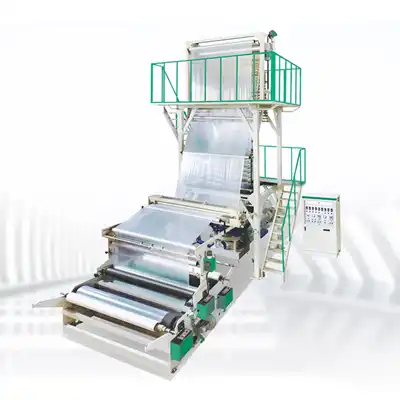
The cooling system is where most transverse thickness problems are born. Automatic air ring technology has changed the game, but only if it is properly implemented. The principle is straightforward: the air ring is divided into multiple independent sections, each with an air valve regulator driven by a stepper motor. An online thickness gauging system measures the film immediately after it is formed, sends data to a computer, and the control actuator adjusts cooling air volume at each point around the circumference. When a section of film is too thick, the valve closes slightly to reduce cooling, allowing that section to remain thicker. When a section is too thin, the valve opens to increase cooling and make the film thicker there.
A well-tuned auto air ring can control radial thickness deviation within 2–5% —close to cast film precision. Without this level of control, you are at the mercy of ambient air drafts, blocked air supply lines, or dirty plenums.
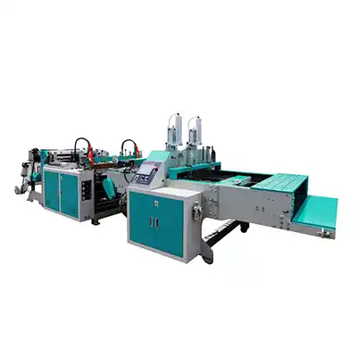
3. Haul-Off Speed Irregularities
Even if your melt flow is perfect and your air ring is balanced, inconsistent nip roll speed will ruin thickness uniformity. The relationship is direct: when haul-off speed fluctuates, the film stretches unevenly in the machine direction. The solution requires a loss-in-weight gravimetric feeding control system, which automatically matches screw rotation speed and haul-off speed to a target value. This technology can cut longitudinal thickness deviation by up to two-thirds.
Manual Adjustments versus Smart Controls
There is a reason why trial-and-error troubleshooting is still common on blown film lines—production pressure forces quick decisions. But here is the hard truth: reactive adjustments made without isolating variables often increase variability rather than reduce it. Structured troubleshooting methodologies, developed through decades of industrial experience, emphasize documenting outcomes and observing system response before making changes.
Some operators still rely on manual die gap adjustments or temperature tweaks at the die lip. These methods have their place, but they cannot match the precision of closed-loop automatic control. The auto die head control system, for instance, uses internally-set thermal expansion bolts. By heating specific segments, you change the local viscosity of the conglomerate liquid—heating one section speeds up flow and makes the film thinner there; cooling it slows flow and makes the film thicker. The advantage is that this approach overcomes the thermal inertia problem that plagues manual die adjustment.
Where Fiim Blown Machine Comes Into the Picture
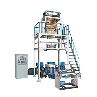
After working through all these possibilities—temperature profiles, air ring calibration, haul-off speed consistency, die gap uniformity—you might still find yourself chasing thickness variations that refuse to disappear. At this point, the problem often is not any single parameter but how the entire extrusion system is configured for your specific material, output target, and film specification. Generic off-the-shelf lines simply cannot adapt to every resin type or application requirement. That is precisely where the concept of Film Blown Machine moves from a theoretical troubleshooting checklist to a practical, engineered solution. Unlike mass-produced equipment that forces you to work around its limitations, Film blown machine emphasizes custom-configured extrusion systems where every component—screw design, die geometry, air ring specification, and control logic—is aligned with your unique production environment.
Compare this to what most manufacturers face: standard lines come with fixed screw L/D ratios, pre-set cooling configurations, and one-size-fits-all control panels. When you push them beyond their design envelope, gauge variation is the predictable result. A properly configured system, by contrast, starts with your melt index requirements, your target output range, and your acceptable thickness tolerance. Then the extruder screw, die head, air ring, and winding tension controls are built around those numbers.
What Customization Actually Looks Like on the Floor
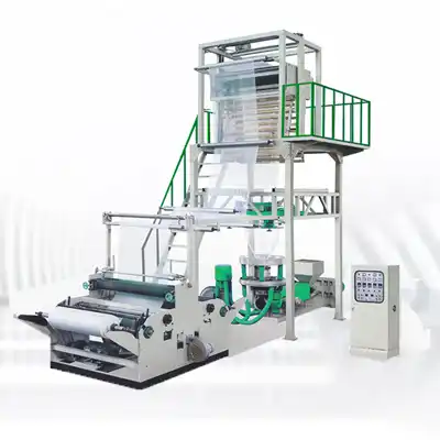
Walk into a plant running a standard film blowing line, and you will see operators constantly adjusting air ring valves and tweaking temperature setpoints, fighting the same battles shift after shift. Walk into a plant with modular, customizable equipment from Yongbang, and the scene looks different. Extrusion parameters like screw speed, melt temperature, and die gap are matched to the specific resin being run. The cooling air ring can be configured for single-lip or dual-lip operation depending on film thickness targets. The haul-off system includes automated tension control that adjusts in real time as roll diameter builds.
A 5–9 layer high-barrier extrusion line, for example, integrates the die head, automatic air ring, and advanced winder into a unified system where thickness profile control is closed-loop from sensor to actuator. That is not a luxury—for packaging films requiring tight barrier properties, it is a necessity.
The Data That Matters
Industry experience across hundreds of blown film lines reveals a consistent pattern: when processors push output rates before stabilizing the process, gauge variation worsens. Effective gauge control depends on alignment among die design, thermal management, draw conditions, and polymer rheology. Automated control systems can handle short-term disturbances, but they cannot fix structural imbalances. Lasting improvement comes from addressing the physical sources of variation—not relying solely on corrective feedback.
And the cost of ignoring this? Poorly wound rolls lead to crushed cores, telescoping, or uneven film tension. Even small edge gauge deviations create compressive stresses that cause wrinkles and blocking. The problem is rarely isolated to a single component; it emerges from interactions among extrusion, cooling, and winding conditions.
One More Thing Before You Go
The blown film extrusion process involves managing a delicate interplay of multiple variables—frost line height, internal bubble pressure, air ring cooling rates, and extruder output must all be perfectly balanced. A failure in any one element leads to bubble instability, wrinkles, or gauge bands. The good news is that each of these variables can be measured, controlled, and optimized.
If you are currently fighting gauge variation on a daily basis, take a step back. Measure your thickness profile across the web and down the roll. Check your die gap uniformity. Verify your air ring alignment. Document your melt temperature stability over eight-hour shifts. Then compare what you find against the ±5–10% thickness deviation range that industry benchmarks consider actionable. If you are outside that range, the fix is not another band-aid adjustment—it is a systematic approach to configuration.
 Brochure Download
 FAQ
FAQ